Panorama Generation
A panorama is formed by stitching together multiple images into one seamless image. A guide on this process can be found here.
Please Note: the estgeotform2d function require Matlab 2022 version.
Part 1
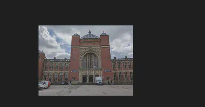
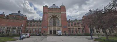
Three images of the Aston Webb building have been provided.
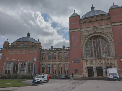 |
 |
 |
|---|
The following steps need to be taken in order to create the panorama.
- Use any preprocessing you like to manipulate the given images. (Here we do not manipulate the given images.)
% Load images
im1 = imread("1.jpg");
im2 = imread("2.jpg");
im3 = imread("3.jpg");
- Detect and match features between image $I(n)$ and $I(n - 1)$.
- Estimate the geometric transformation $T(n)$, that maps $I(n)$ to $I(n - 1)$.
- Compute the transformation that maps $I(n)$ into the panorama image as $T(1) * T(2) * ... * T(n - 1) * T(n)$.
%% Register Image Pairs

% Initialize features for im1. Here we convert the original image to a grayscale image
grayImage = im2gray(im1);

points = detectSURFFeatures(grayImage);
[features, points] = extractFeatures(grayImage,points);

% Initialize all the transformations to the identity matrix. Note that the
% projective transformation is used here because the building images are fairly
% close to the camera. For scenes captured from a further distance, you can use
% affine transformations.
numImages = 3;
tforms(numImages) = projtform2d;

% Initialize variable to hold image sizes.
imageSize = zeros(numImages,2);

% Iterate over remaining image pairs
for n = 2:numImages
    % Store points and features for I(n-1).
    pointsPrevious = points;
    featuresPrevious = features;

    % Read I(n).
    if n == 2
        I = im2;
    else
        I = im3;
    end

    % Convert image to grayscale.
    grayImage = im2gray(I);

    % Save image size.
    imageSize(n,:) = size(grayImage);

    % Detect and extract SURF features for I(n).
    points = detectSURFFeatures(grayImage);
    [features, points] = extractFeatures(grayImage, points);

    % Find correspondences between I(n) and I(n-1).
    indexPairs = matchFeatures(features, featuresPrevious, 'Unique', true);

    matchedPoints = points(indexPairs(:,1), :);
    matchedPointsPrev = pointsPrevious(indexPairs(:,2), :);

    % Estimate the transformation between I(n) and I(n-1).
    tforms(n) = estgeotform2d(matchedPoints, matchedPointsPrev,"projective" ...
        , 'Confidence', 99, 'MaxNumTrials', 2000);
    %     tforms(n) = estgeotform2d(matchedPoints, matchedPointsPrev,...
    %         'projective', 'Confidence', 99.9, 'MaxNumTrials', 2000);

    % Compute T(1) * T(2) * ... * T(n-1) * T(n).
    tforms(n).A = double(tforms(n-1).A) * double(tforms(n).A);
end

% Compute the output limits for each transformation.
for i = 1:numel(tforms)
    [xlim(i,:), ylim(i,:)] = outputLimits(tforms(i), [1 imageSize(i,2)], [1 imageSize(i,1)]);
end

avgXLim = mean(xlim, 2);
[~,idx] = sort(avgXLim);
centerIdx = floor((numel(tforms)+1)/2);
centerImageIdx = idx(centerIdx);

Tinv = invert(tforms(centerImageIdx));
for i = 1:numel(tforms)
    tforms(i).A = Tinv.A * tforms(i).A;
end
- Utilise the
imwarpfunction to align the images into the panorama.
%% Initialize the Panorama
for i = 1:numel(tforms)
    [xlim(i,:), ylim(i,:)] = outputLimits(tforms(i), [1 imageSize(i,2)], [1 imageSize(i,1)]);
end

maxImageSize = max(imageSize);

% Find the minimum and maximum output limits.
xMin = min([1; xlim(:)]);
xMax = max([maxImageSize(2); xlim(:)]);

yMin = min([1; ylim(:)]);
yMax = max([maxImageSize(1); ylim(:)]);

% Width and height of panorama.
width  = round(xMax - xMin);
height = round(yMax - yMin);

% Initialize the "empty" panorama.
panorama = zeros([height width 3], 'like', I);

%% Create the Panorama

blender = vision.AlphaBlender('Operation', 'Binary mask', ...
    'MaskSource', 'Input port');

% Create a 2-D spatial reference object defining the size of the panorama.
xLimits = [xMin xMax];
yLimits = [yMin yMax];
panoramaView = imref2d([height width], xLimits, yLimits);

% Create the panorama.
for i = 1:numImages

    if i == 1
        I = im1;
    elseif i == 2
        I = im2;
    else
        I = im3;
    end

    %     I = readimage(buildingScene, i);

    % Transform I into the panorama.
    warpedImage = imwarp(I, tforms(i), 'OutputView', panoramaView);
    figure();
    imshow(warpedImage);
    imwrite(warpedImage,['transform' , num2str(i), '.png'])
    % Generate a binary mask.
    mask = imwarp(true(size(I,1),size(I,2)), tforms(i), 'OutputView', panoramaView);

    % Overlay the warpedImage onto the panorama.
    panorama = step(blender, panorama, warpedImage, mask);
end

figure
imshow(panorama)
imwrite(panorama,"result.png")
Results
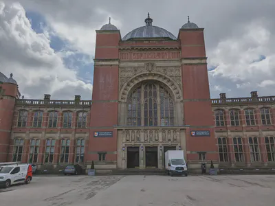
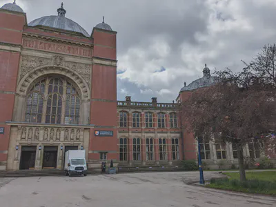
- Figure showing undistorted input images.
| Original Input |
|
|
|
|---|---|---|---|
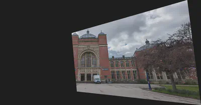
| Transform images |
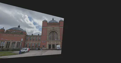 |
 |
 |
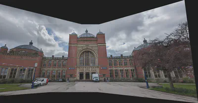
- Figure showing complete panorama.
- A written explanation of the steps taken in the report, stating which functions you used, why you used them and a short explanation of how they work.
Step 1: Use any preprocessing you like to manipulate the given images.
- In this step, I use build-in
im2grayfunction to convert the RGB image to grayscale.im2grayfunction works by removing hue and saturation information while preserving lightness. I use this function to reduce the dimensions of image data, and reduce the cost of calculation.
Step 2: Detect and match features between image $I(n)$ and $I(n - 1)$.
- In this step, I use build-in
detectSURFFeaturesfunction to detect features.detectSURFFeaturesfunction implements the Speeded-Up Robust Features (SURF) algorithm to find blob features. I use this function because it is more efficient compared to other algorithms. I tried other algorithms, such as “Minimum Eigenvalue”, “KAZE”, “FAST” and so on, their results are not ideal. Meanwhile, I need to detect features in images to be ready for matching features. - Also, I use build-in
matchFeaturesfunction to match features between image $I(n)$ and $I(n - 1)$.matchFeaturesfunction helps to find corresponding interest points between a pair of images using local neighbhorhoods and the Harris algorithm. I use this function to match features between images so that I can get the transformation matrix.
Step 3: Estimate the geometric transformation, $T(n)$, that maps $I(n)$ to $I(n - 1)$.
- In this step, I use build-in
estgeotform2dfunction to estimate the geometric transformation.estgeotform2dfunction estimates a 2-D geometric transformation between two images by mapping the inliers in the matched points from one image to the inliers in the matched points from another image. At here, I set the transformation type is projective.
Step 4: Compute the transformation that maps $I(n)$ into the panorama image as $T(1) * T(2) * ... * T(n - 1) * T(n)$. I do not use any function in this step.
Step 5: Utilise the imWarp function to align the images into the panorama.
- In this step, I use build-in
imwarpfunction returns the transformed image according to the geometric transformation. Then, I can overlay the transformed images onto the panorama.
Part 2
The panorama which has been produced is not a uniform shape. Write an algorithm from scratch that iteratively crops the image so that no black areas are included. Your algorithm should preserve as much of the non-black areas of the image as possible and work with any provided panorama.
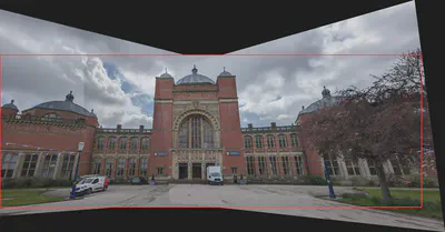
- A figure showing the original panorama overlaid with (red) lines representing the cropped area
- The cropped panorama
Algorithm explanation
Step 1: Using build-in im2gray and imbinarize functions to convert the RGB image to binary image. See below figure for result.

Step 2: Using build-in imfill function to fill the holes in the binary image. See below figure for result.

Step 3: Setting two scanlines $S_{up}$ and $S_{down}$ with a length of $l$, where $l$ is equal to the length of the original picture in the horizontal direction.
Step 4: Let the midpoint of the scanlines follow the central axis of the vertical direction of the panorama, and scan from the top and bottom respectively. Once the pixel values on the scanlines are all $1$, record the ordinate of the scanlines at this time as $b_{up}$ and $b_{down}$. The $b_{up}$ and $b_{down}$ are the upper and lower boundary coordinates of the clipping region.
Step 5: Now, we have know the upper and lower boundary coordinates. Assuming the coordinate of the center point of the panorama is $(c_x,c_y)$. Then, firing two rays from points $(c_x, b_{up})$ and $(c_x, b_{down})$ in the horizontal left and right directions. Once a value of 0 is detected, record the position $b_{left}$ and $b_{right}$ of the ray endpoint at this time as the left and right boundaries. (Note: The left and right boundaries are calculated independently. For example, when the position of the left boundary is confirmed, the search of the right boundary will not stop)
Step 6: Finally, we get the four vertices coordinates of the rectangular clipping region. They are $(b_{up}, b_{left})$, $(b_{up}, b_{right})$, $(b_{down}, b_{left})$, $(b_{down}, b_{right})$. Then we can crop picture.
Source code
%% Task 1.1.2
% function  cutBackground

% function ICut = cutBackground(I)

% figure
% imshow(ICut)
% imwrite(ICut,"result_cut.png")

panorama = imread("result.png");
I = panorama;

grayImage = im2gray(I);
grayImage = imbinarize(grayImage,0.01);
% figure
% imshow(grayImage);
imwrite(grayImage,"biImage.png")
grayImage = imfill(grayImage,"holes");
% figure
% imshow(grayImage);
imwrite(grayImage,"biImage_fillholes.png")


[row, column] = size(grayImage);
columnCenter = round(column/2);


row_im2 = 3024;
column_im2 = 4032;

% up and low
width_im2 = round(column_im2/2);
left = columnCenter - width_im2;
right = columnCenter + width_im2;

iPixel = 1;
signal = 1;
while signal
    up = iPixel;
    a = all(grayImage(up, left:right));

    if a
        signal = 0;
    else
        iPixel = iPixel + 1;
    end
end

iPixel = 0;
signal = 1;
while signal
    low = row - iPixel;
    b = all(grayImage(low, left:right));

    if b
        signal = 0;
    else
        iPixel = iPixel + 1;
    end
end


check = grayImage(up:low,:);

% right and left
iPixel = 1;
signal_right = 1;
while signal_right
    right = columnCenter + iPixel;

    if grayImage(up, right) == 0 || grayImage(low, right) == 0 || right == column
        signal_right = 0;
    else
        iPixel = iPixel + 1;
    end

end

iPixel = 1;
signal_left = 1;
while signal_left
    left = columnCenter - iPixel;

    if grayImage(up, left) == 0 || grayImage(low, left) == 0 || left == 1
        signal_left = 0;
    else
        iPixel = iPixel + 1;
    end

end

figure
line  = I;
line(up:up+10,left:right, 1) = 255;
line(up:up+10,left:right, 2) = 0;
line(up:up+10,left:right, 3) = 0;

line(low-10:low,left:right, 1) = 255;
line(low-10:low,left:right, 2) = 0;
line(low-10:low,left:right, 3) = 0;

line(up:low,left:left+10, 1) = 255;
line(up:low,left:left+10, 2) = 0;
line(up:low,left:left+10, 3) = 0;

line(up:low,right-10:right, 1) = 255;
line(up:low,right-10:right, 2) = 0;
line(up:low,right-10:right, 3) = 0;
imshow(line);
imwrite(line,"result_cutArea.png")


ICut = I(up:low,left:right,:);

figure
imshow(ICut)
imwrite(ICut,"result_cut.png")
% end